Kenosha Reuse Discussion Board > ZION, IL
> Commercial
> Mechanical
> Refurbished
> No Warranty
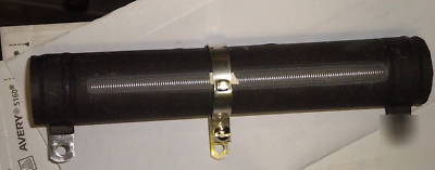
> New vishay dale wirewound resistor hla-130-07Z 130W
New vishay dale wirewound resistor hla-130-07Z 130W
Wirewound Resistors, Industrial Power, Adjustable Tapped Tubular
Adjustable resistor or voltage divider High temperature silicon coating Can be used to quickly obtain odd resistance values One or more adjustable lugs can be provided for voltage divider applications Can be used as multi-tap resistor
STANDARD ELECTRICAL SPECIFICATIONS
MODEL HLA-12 HLA-20 HLA-25 HLA-26 HLA-50 HLA-51 HLA-60 HLA-65 HLA-80 HLA-100 HLA-120 HLA-130 HLA-160 HLA-175 HLA-225 POWER RATING P25 C W 12 20 25 26 50 51 60 65 80 100 120 130 160 175 225 RESISTANCE RANGE 5% 1.0 - 10k 1.0 - 18k 1.0 - 23k 1.0 - 31k 1.0 - 57k 1.0 - 95k 1.0 - 74k 1.0 - 130k 1.0 - 111k 1.0 - 132k 1.0 - 180k 1.0 - 192k 1.0 - 249k 1.0 - 398k 1.0 - 337k
WEIGHT ( Ty p i c a l ) g 6.69 12.57 20.72 15.34 42.08 51.96 65.64 64.82 121.58 91.37 183.82 192.36 245.86 250.80 309.97
PARAMETER Temperature Coefficient Short Time Overload Maximum Working Voltage Operating Temperature Range UNIT p p m / C V C HLA RESISTOR CHARACTERISTICS 90 for .1 to .99; 50 for 1 to 9.9; 30 for 10 and above 10 x rated power for 5 seconds (P x R)1/2 - 55 / + 350
* Short Time Overload is rated without adjustable lug attached.
Element: Copper-nickel alloy or nickel-chrome alloy, depending on resistance value Core: Ceramic, steatite Coating: Special high temperature silicone Standard Terminals: Model "Z" terminals are tinned steel Terminal Bands: Steel Part Marking: DALE, Model, Wattage, Value, Tolerance, Date Code
HLA-225 MODEL 07 TERMINAL Z TERMINAL FINISH 2 0 0 RESISTANCE 5% TOLERANCE %
For technical questions, contact ****@vishay.com
Document Number: 30211 Revision 28-Mar-02
MODEL DIMENSIONS in inches [millimeters] CORE DIMENSIONS MOUNTING HARDWARE OPTIONS 101, 204, 301 101, 203, 301 101, 203, 301 101, 203, 301 101, 203, 301 102, 206, 303 102, 206, 303 102, 206, 303 103, 205, 303 102, 206, 303 103, 205, 303 103, 205, 303 103, 205, 303 103, 205, 303 103, 205, 303
TERMINAL DISTANCE DESIGNATION TERMINAL BETWEEN A I.D. LENGTH SETBACK TERMINALS ADJ. (Max.) 0.031 [0.79] 0.31 [0.79] (REF) STANDARD OPTIONAL SLIDER 0.062 [1.59] O.D. HLA-12 0.406 [10.32] 1.750 [44.45] 0.313 [7.94] 0.188 [4.76] 0.094 [2.38] 1.187 05Z 14 N 70 HLA-20 0.563 [14.29] 2.000 [50.80] 0.438 [11.11] 0.313 [7.94] 0.094 [2.38] 1.437 02Z 14 N 71 HLA-25 0.688 [17.46] 2.000 [50.80] 0.563 [14.29] 0.313 [7.94] 0.094 [2.38] 1.312 06Z 15 N 72 HLA-26 0.563 [14.29] 3.000 [76.20] 0.438 [11.11] 0.313 [7.94] 0.094 [2.38] 2.437 02Z 14 N 71 HLA-50 0.688 [17.46] 4.000 [101.60] 0.563 [14.29] 0.313 [7.94] 0.094 [2.38] 3.312 15 N 06Z 72 HLA-51 0.906 [23.02] 3.500 [88.90] 0.750 [19.05] 0.500 [12.70] 0.125 [2.38] 2.75 06Z 15 N 73 HLA-60 0.906 [23.02] 4.000 [101.60] 0.750 [19.05] 0.500 [12.70] 0.125 [3.18] 3.250 06Z 15 N 73 HLA-65 0.906 [23.02] 4.500 [114.30] 0.750 [19.05] 0.500 [12.70] 0.125 [3.18] 3.750 15 N 06Z 73 HLA-80 1.313 [33.34] 4.000 [101.60] 1.125 [28.58] 0.750 [19.05] 0.219 [5.56] 2.812 15 N 07Z 74 A HLA-100 0.906 [23.02] 6.500 [165.10] 0.750 [19.05] 0.500 [12.70] 0.125 [3.18] 5.750 06Z 15 N 73 4.812 07Z 15 N 74 (Includes Coating and HLA-120 1.313 [33.34] 6.000 [152.40] 1.125 [28.58] 0.750 [19.05] 0.219 [5.56] Terminal Band) HLA-130 1.313 [33.34] 6.500 [165.10] 1.125 [28.58] 0.750 [19.05] 0.219 [5.56] 5.312 07Z 15 N 74 HLA-160 1.313 [33.34] 8.000 [203.20] 1.125 [28.58] 0.750 [19.05] 0.219 [5.56] 6.812 07Z 15 N 74 HLA-175 1.313 [33.34] 8.500 [215.90] 1.125 [28.58] 0.750 [19.05] 0.219 [5.56] 7.312 07Z 15 N 74 HLA-225 1.313 [33.34] 10.500 [266.70] 1.125 [28.58] 0.750 [19.05] 0.219 [5.56] 9.312 07Z 15 N 74
Moving Adjustable Lugs: The coating protects the resistance wire from shifting and shorting to other turns during adjustment. However, the following three steps should always be taken whenever adjustments are made: (1) Turn off power to avoid possible operator injury and damage to the unit. (2) Loosen adjustable lug until it will slide completely free, without touching the exposed wire. (3) When adjustment point has been selected, retighten lug only enough to assure a firm contact, do not tighten beyond this point. Failure to follow these three steps in order can result in damage to the resistor.
SLIDER MODEL NUMBER 70 71 72 73 74
0.188 [4.76] 0.516 [13.10] 0.125 [3.18] 0.250 [6.35] 0.594 [15.08] 0.156 [3.96] 0.250 [6.35] 0.719 [18.26] 0.141 [3.58] 0.250 [6.35] 0.781 [19.84] 0.141 [3.58] 0.313 [7.94] 0.781 [19.84] 0.170 [4.32]
A C Style 02 thru 07 B D A C Styles 14 & 15
02 0.188 [4.76] 0.406 [10.32] 0.093 [2.36] 0.020 [0.51]
05 0.188 [4.76] 0.438 [11.11] 0.104 [2.64] 0.020 [0.51]
TERMINAL TYPE 06 07 0.250 0.375 [6.35] [9.53] 0.563 0.625 [14.29] [15.88] 0.166 0.173 [4.22] [4.39] 0.020 0.020 [0.51] [0.51]
14 0.188 [4.76] 0.563 [14.29] 0.050 [1.27] 0.020 [0.51]
15 0.250 [6.35] 0.594 [15.08 0.065 [1.65] 0.031 [0.79]
HLA resistors use same mounting hardware as standard HL resistors, see HL data sheet for mounting hardware dimensions.
Finish for terminal style 14 & 15 is limited to nickel plated steel (N), all other terminals will be steel supplied with tinned solder finish (Z).
150 250 350 AMBIENT TEMPERATURE IN C