Kenosha Reuse Discussion Board > KENOSHA, WI
> Commercial
> Automative
> Used
> Lecroy 4 ch 1GHZ digital oscilloscope w/ probes, 8 gs/s
Lecroy 4 ch 1GHZ digital oscilloscope w/ probes, 8 gs/s
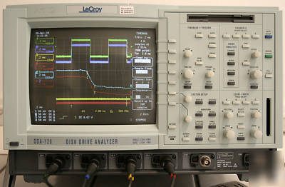
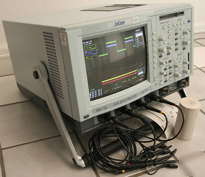
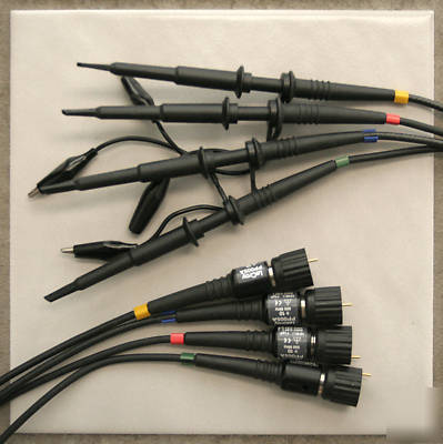
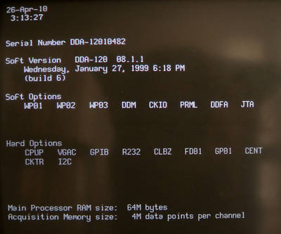
LeCroy DDA-120 Color 1 GHz 4 Channel Digital Storage Oscilloscope (DSO), 4 LeCroy PP005A 500 MHz Probes (with shown accessories), power cord, and two full rolls of printer paper (one loaded in printer).
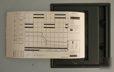
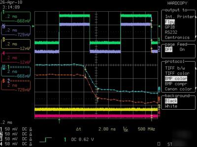
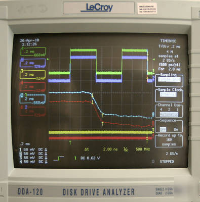
8 GSa/sec (and 16 Mpts.) on one channel, 4 GSa/sec (and 8 Mpts.) on two channels, or 2 GSa/sec (and 4 Mpts.) on 4 channels, automatically or manually selected. The scope has LeCroy's essential features including Zoom and Math channels, and Smart Triggers. Probes include grabber clips and ground clips, and are color coded with Yellow, Red, Blue, and Green bands to match the displayed waveforms. Waveforms can be printed using the internal printer, external color printer, or saved as .BMP files (see picture) or raw data to the floppy. Cosmetically, the paint has a few minor scuffs, but everything works, and is guaranteed to. I will also email you the Users Manual in .PDF format. This DDA-120 model is an LC584AXL with additional Disk Drive Analysis features (hence the labeling) that you will never use (as I never have), but this is the best and easiest to use oscilloscope that I have ever used. The scope will be packed very securely with Instapak foam-in-place.
Calibration is current until 09/08/10.
@ 50 Ohm: DC to 1 GHz (2 mV/div: DC to 200 MHz,
5 mV/div: DC to 600 MHz);@ 1 M Ohm: DC: DC to 500 MHz typical at
PP005 probe tip; DC to 1 GHz at optional AP020 1 GHz FET probe
Sensitivity: 2 mV/div to 1 V/div, 50 Ohm, fully variable; 2
mV/div to 10 V/div, 1 M Ohm, fully variable.
Offset Range: 20 V across the whole sensitivity range when
using the AP020/AP022 active probe.
1.0 to 10 V/div: 100 V (1 M Ohm only)
Scale Factors: Wide range of probe attenuation factors available
DC Accuracy: ?}(2% full-scale + 1% offset value) at gain
Bandwidth Limiter: 25 MHz and 200 MHz typical
Input Coupling: AC (>10 Hz typical), DC, GND
Input Impedance: 10 M Ohm/11 pF (system capacitance using
Max. Input: 50 Ohm: 5 V DC (500 mW) or 5 V rms; 1 M Ohm:
400 V max (DC + peak AC ?10 kHz).
SMARTMemory: A total memory management system that
dynamically manages acquisition memory to guarantee that
signals are always sampled at the highest possible sample rate
and that system RAM and microprocessor resources are always
System Random Access Memory: 64 M
Random Interleaved Sampling (RIS): For repetitive signals from
Single Shot: For transient and repetitive signals from 500 ps/div
(1 channel), 1 ns/div (2 channels), 2 ns/div (4 channels)
Sequence: Stores multiple events, each time-stamped, in
segmented acquisition memories.
Dead Time between Segments: Typically 30 ?s, maximum
Number of Segments Available: 2 to 6000
Timebases: Main and up to four Zoom Traces
Time/Div Range: 500 ps/div at 8 GS/s
Interpolator Resolution: 10 ps
Roll Mode: Ranges from 500 ms to 1000 s/div.
External Clock: 50 to 500 MHz rear panel, fixed frequency clock
input (DC to 500 MHz (_ 20 ns rise/fall time)
External Reference: 10 MHz rear panel input
Trigger Modes: NORMAL, AUTO, SINGLE, and STOP
Sources: CH1, CH2, CH3, CH4, Line, Ext, Ext/5. Slope, Level,
and Coupling are unique to each source.
Slope: Positive, Negative, Bi-Slope (Window in and out)
Coupling: AC, DC, HF, LFREJ, HFREJ
Pre-trigger Recording: 0 to 100% of full scale (adjustable in 1%
Post-trigger Delay: 0 to 10 000 divisions (adjustable in 0.1 div
Hold-off by Time: 2 ns to 20 s
Holdoff by Events: 0 to 99 999 999
Internal Trigger Range: 5 screen divisions
EXT Trigger Max Input: 10 M /11 pF at probe tip
(PP005): 400 V (DC + peak AC ?10 kHz); 50 1%; 5 V DC
EXT Trigger Range: 0.5 V; 2.5 V with EXT/5
Trigger Timing: Trigger Date and Time are listed in the
Trigger Comparator: Optional ECL rear panel output.
Alternatively, the calibrator output can provide a trigger output or
Pattern: Trigger on the logic combination of five inputs CH 1,
CH 2, CH 3, CH 4, and EXT Trigger, where each source can be
defined as High, Low, or Don't Care. The Trigger can be
defined as the beginning or end of the specified pattern.
Signal or Pattern Width: Trigger on glitches as short as 600 ps
or on pulse widths 600 ps to 20 s.
Signal or Pattern Interval: Trigger on interval between two
limits; able to be selected from 2 ns to 20 s.
Dropout: Trigger if the input signal drops out for longer than a
Qualified: Trigger on any source only if a given state (or
transition) has occurred on another source (the delay between
these events can be defined as a number of events on the trigger
channel or as a time interval).
TV: Allows selection of up to 1500 lines and odd or even fields
synchronized for PAL, SECAM, NTSC, or nonstandard video.
Runt: Trigger on positive or negative runts between two limits
able to be selected from 600 ps to 20 s.
Slew Rate: Trigger on rising or falling edges between 600 ps and
Exclusion Triggering: Can be performed in Glitch, Interval,
Runt, and Slew-Rate Trigger modes (triggers on intermittent
faults by specifying the normal width, period, level or slew of a
signal). The DDA will trigger only on aberrations shorter or longer
Sector Pulse: Trigger on the nth sector pulse (1 to 50) after
Index, which can be defined individually as positive or negative
Servo Gate: Trigger on the nth servo gate after Index, and on
every mth thereafter; Servo Gate and Index can be individually
defined as positive or negative polarity.
PES Window: Trigger on Position Error Signal (PES) exceeding
a selected voltage window; servo gate can be selected as an
additional criterion before a PES window may occur.
Read Gate: Can trigger on any Read Gate longer than a
specified Sector ID field length, adjustable from 100 ns to 50 ?s
Automatically sets sensitivity, vertical offset and timebase on all
Autosetup Time: Two to three seconds
Vertical Find: Automatically sets sensitivity and offset for
One PP005 Passive Probe per channel: DC to 500 MHz typical at
Passive Probe calibration: Max. 1 V into 1 M Ohm; 500 mV into
50 Ohm; frequency and amplitude able
to be programmed; pulse or square
wave able to be selected; rise and
Screen Type: Color 10-inch Raster Scan CRT,
Display Area: 170 mm x 125 mm.
Controls: Rear panel presets for position, brightness
and contrast; Front panel menu controls for brightness and color
Grid Styles: Single, Dual, Quad, Octal, XY, Single + XY, Dual +
XY, and Full Screen an enlarged view of each grid style
Graticules: Internally generated; separate intensity control for
grids and waveforms; selectable blending of grid with displayed
Waveform Style: Dot Join with optional sample point highlight or
Persistence Modes: Color Graded and Analog Persistence,
infinite or variable with decay over time
Trace Display: Opaque or transparent mode, with overlap
Number of Traces: Eight (any mix of channels, memories or
Real-time Clock: Date, hours, minutes, seconds.
External Monitor: Rear panel 15-pin socket for VGA compatible
Vertical Zoom: Up to five times vertical expansion (50 times with
averaging, up to 40 V/div sensitivity)
Horizontal Zoom: up to 0.4 points/division
Microprocessor: 192 MHz PowerPC 603e
Persistence Data Map Memory: 16 bits per displayed pixel
Up to four processing functions may be performed at the same
time. Standard functions available are: Add, Subtract, Multiply,
Divide, Negate, Identity, Summation Averaging and (Sine x)/x.
The source information for a math function trace can be data
from an acquisition channel or from another math function trace.
This allows display of traces that daisy chain math functions.
Average: Up to 106 averages possible
Extrema: Roof, Floor, or Envelope values from 1 to 106 sweeps.
ERES: Six low-pass digital filters provide up to 11-bit vertical
resolution. Sampled data is always available, even when a trace
FFT: Spectrum Analysis with five windowing functions and FFT
Resample: Deskew feature that allows a signal to be resampled
and adjusted in time relative to another signal.
Statistical Diagnostics: Permits in-depth diagnostics on
waveform parameters. Live histogramming of any waveform
parameter measurement is possible. The histogram can be
autoscaled to display the center and width of the distribution. Any
of these processes can be invoked without losing the data.
Waveform Memory: Up to four 16-bit memories (M1, M2, M3,
M4), whose length corresponds to the length of the channel
Zoom and Math Memory: Up to four 16-bit waveform
processing memories (A, B, C, D), whose length corresponds to
the length of the channel acquisition memory
Setup Memory: Four non-volatile memories (Optional Memory
Cards, Flash Disks, or removable Hard Disks may also be used
for high-capacity waveform and setup storage.)
Relative Time: A pair of arrow cursors measure time differences
and voltage differences relative to each other
Relative Voltage: A pair of line cursors measure voltage
Absolute Time: A cross-hair marker measures time relative to
the trigger, and voltage with respect to ground
Absolute Voltage: Reference bar measures voltage with respect
A wide range of pulse parameter measurements are available.
These are categorized for ease of use. The categories include
Pulse, Horizontal, and Vertical parameters. Basic statistical
measurements, included as standard, (average, highest, lowest,
and standard deviation) can be made on these parameter
measurements in order to understand their distribution. Pass/Fail
Testing and Waveform Limit testing, using masks, can be
performed. Test conditions can be expressed as either waveform
parameter limits, waveform shape limits (mask) or a combination
of both. Any failure can cause preprogrammed actions such as
Hardcopy, Save, GPIB service request, logic pulse out, audible
beep, or any combination of the above.
Remote Control: By GPIB and RS-232-C for
all front panel controls and internal functions
RS-232-C Port: Asynchronous up to
115.2 Kb/s for computer or terminal
control, or printer or plotter connection
GPIB Port: (IEEE-488.1) Configurable as
transmitter/receiver for computer control
and fast data transfer; command language compliant with IEEE-
Centronics Port: Hardcopy interface
PC Card (PCMCIA I/II/III Ports): Optional for memory cards,
flash cards, and removable hard disks
Floppy Disk: High density 3.5-inch floppy disk drive (DOS
VGA Compatible Display: 15-pin D-type VGA compatible
connector for external color display. You may experience
flickering if you connect an LCD projector to the VGA output.
Hardcopy: TIFF and BMP formats available for import to Desktop
Publishing programs; HPGL protocol for vector screen files
_ B/W: HP LaserJet, HP DeskJet 500, Epson FX
_ Color: HP DeskJet 550C; Epson Stylus; Canon 200, 600, 800
_ Internal, high resolution graphics printer standard; stripchart
output format with two meters per division also available
Output Formats: Binary, or ASCII waveform output compatible
with spreadsheets, MATLAB, MathCad
Auto-calibration: Ensures specified DC and timing accuracy
Temperature: 5 to 40 C (41 to 104 F)
Humidity: 80% for temperatures up to 31 C, decreasing linearly
to 50% relative humidity at 40 C
Shock and Vibration: Conforms to selected sections of
Power Requirements: 90 to 132 V AC, or 180 to 250 V AC; 45
to 66 Hz; automatic AC voltage selection;
Battery Backup: Front panel settings maintained for two years
Dimensions: (HWD) 10.4 x 15.65 x 17.85 inches (264 x 397 x
CE Declaration of Conformity: The oscilloscope meets
requirements of EMC Directive 89/336/EEC for Electromagnetic
Compatibility and Low Voltage Directive 73/23/EEC for Product
_ EMC: Conforms to EN 50081-1: 1992 (Emissions),
See Declaration of Conformity Certificate for details.
_ Low Voltage Directive: Conforms to EN 61010-1: 1993 +
Amd. 2: 1995, Safety requirements for electrical equipment
for measurement, control, and laboratory use.
The DDA has been qualified to the following EN 61010-1
Installation (Overvoltage) Category II