Kenosha Reuse Discussion Board > GURNEE, IL
> Commercial
> Industrial
> New
> Plus Warranty
> GM3VLB "poor man's hf aerial / antenna analyser"
GM3VLB "poor man's hf aerial / antenna analyser"
Most radio amateurs want their antennas to be resonant at or near the intended operating frequency. At resonance, the input impedance becomes purely resistive, i.e. there is no capacitive or inductive reactance. Furthermore, most amateurs would also like to know the value of this input resistance. It is rarely, if ever, the 50 ohms generally needed for perfect matching (and maximum power transfer). A well-designed, resonant HF mobile antenna may for example show an input resistance of 20 ohms - equivalent to an SWR of 2.5 to 1. Matching such an antenna, at its input is very simple (built-in ATUs do NOT match the antenna...they simply match the complex antenna + coax!). Any unmatched mobile antenna showing an SWR of 1 : 1 should be regarded with grave suspicion, as it implies large system losses.
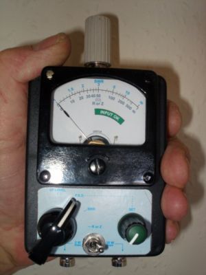
So what are the features of this analyser? First of all, it does not need any separate source of power (no batteries). It uses a top-quality (Russian military), highly linear, 50uA meter in a bridge arrangement to accurately measure SWR of both resistive and inductive loads. It will indicate resonance by determining minimum SWR as antenna physical factors are varied. It will accurately measure antenna input resistance at resonance, thus indicating the matching required.
In use, the antenna is connected to the BNC socket at the top of the analyser (not visible in the pic'). Reduced power (from the transmitter) is fed to one of two BNC input sockets selectable by a switch, either 2W (QRP) or 20W (maximum) via an internal 10dB attenuator. Input (I/P) level (ideal is 1W, or 10W via attenuator)) is checked in 4-way switch position 1, full-scale deflection (FSD) is adjusted by the "SET" control in position 2, SWR is measured in position 3 and input resistance (or impedance) in position 4....The analyser is extremely simple to use. It is primarily intended for use on the HF amateur bands but has been found to give useful indication at 144MHz. It comes with step-by-step instructions.
NOTE: Another desirable feature of this instrument, is that high SWR presents NO risk of damage to the transmitter. Even if the antenna input socket is open-circuit, the impedance presented to the transmitter is 100 ohms (an SWR of only 2 : 1). Similarly , if the input is short-circuit the impedance is 33.3 ohms (an SWR of only 1.5 : 1). Both values are thus well within the safe operating limits of all transmitters.