Kenosha Reuse Discussion Board > GURNEE, IL
> Commercial
> Automative
> Aeroflex atc-1400A aviation test set transponder / dme
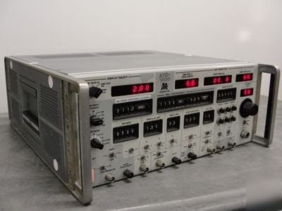
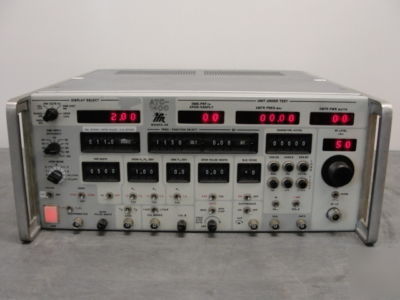
Aeroflex atc-1400A aviation test set transponder / dme
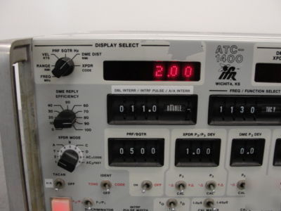
AEROFLEX (IFR / MARCONI) ATC-1400A
AVIATION TEST SET, TRANSPONDER / DME
The Aeroflex / IFR ATC-1400A Aviation Test Set is a microprocessor based test set designed for testing and calibrating DME (Distance Measuring Equipment), ATC (Air Traffic Control) Transponder aircraft equipment, and ARINC 568 Digital DME Indicators. It can be operated manually using front panel controls and switches, or remotely by ATE (Automatic Test Equipment) control through the GPIB (General Purpose Interface Bus).
When interfaced with the T-1401, S-1403DL or SI-1404 accessory units, the ATC-1400A becomes a comprehensive test system for TACAN, Mode 4 IFF transponder and Mode S transponder avionics equipment.
Key Features of the ATC-1400A include:
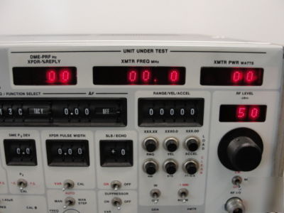
* Continuous display of UUT, PRF, % Reply, Transmitter Frequency and Power
* Variable SLS and Echo Pulse Level
* Digital display of decoded transponder reply pulses
* Acceleration, velocity and range DME Modes
* Variable interference and double interrogation pulse position
* Remote operation via IEEE 488-1978 bus
The IFR / Aeroflex ATC-1400A incorporates the following capabilities:
* Frequency Select Modes: User selectable L-Band Output Frequency can be selected by direct MHz, VOR paired and TACAN channel designation.
* F Capability: The selected frequency can be varied 9.99 MHz in 0.01 MHz increments.
* Manual/Automatic Stepping: The selected frequency can be automatically varied in 1 MHz increments.
* Suppressor ON/OFF: The suppressor pulse output may be switched ON or OFF and the level adjusted from the front panel.
* Range Delay: Switch selectable -1.00 to 399.90 NMi
* Velocity: Select inbound or outbound. Inbound and outbound velocity decrements range to 0 NM, then increments range 9990 KTS.
* Acceleration: Non-zero acceleration decrements the selected velocity to 0 KTS, then increments velocity to 9990 KTS.
* Squitter: Digitally implemented to provide stable rate distribution and repeatability
* TACAN Simulation: When TACAN/On is selected, output pulses are AM modulated with 15 and 135 Hz signals.
* Echo Pulses: Front panel selectable
* Ident Pulses: Select continuous pulse or Morse code from front panel
* Pulse Characteristics: DME Pulses are formed by filtering, which provides superior representation of Gaussian shaped pulses.
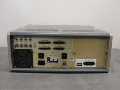
* DME Serial Data Interface: The serial BCD distance word is generated to correspond to the range distance programmed in the test set. This serial BCD word is available at the back panel through a 25 pin D type connector.
* Frequency Channelling: The 2-out-of-5 VOR Paired Channel Frequency is available for control of the DME UUT when the test set is in the automatic frequency stepping mode. ARINC 568 compatible
* Transponder Mode: Modes 1, 2, T, A, B, C, D, AC1 and AC2 are available.
* Variable Pulse Spacing: P2 and P3 pulse spacing may be varied in the + or - direction or may be selected to the calibrated spacing from individual switches on the front panel.
* Pulse Width: The generated pulse width may be varied or selected for a calibrated width by a front panel switch.
* Side Lobe Suppression: On/Off selectable P2 pulse
* Interference/DBL Interrogation: The Interference pulse and double interrogation functions are combined in a single switch and are exclusively selectable.
* UUT Pulse Spacing Detector: Transponder reply pulses are verified for proper position by selection of a narrow window. A wide window is provided when pulse position accuracy verification is not desired.
* Suppression Recovery: Selection of double interrogation and suppressor pulse provides a single interrogation after suppressor pulse spacing may be varied by interference/DBL interrogation switch.
* Range Delay: Switch selectable -1 nmi Range for indicator calibration. When selecting -1 nmi feature, 1 nmi is subtracted from the programmable range of 0 to 399.99 nmi. Actual range of UUT is displayed on DISPLAY SELECT Readout (43), not selected range.
* Velocity: Selected as inbound or outbound. Inbound velocity decrements selected range to zero and then increments range to 400.00 nmi. Outbound velocity increments selected range to 400.00 nmi, then decrements to zero nmi.
* Acceleration: Non-zero acceleration decrements selected velocity to 0 then increments to 4000 KTs.
* Squitter: Squitter is digitally implemented to provide stable rate and distribution, as well as repeatability.
* TACAN Simulation: When TACAN is selected, output pulses are AM modulated with 15 and 135 Hz signals. TACAN main burst and auxiliary burst signals are generated representing a bearing of 180 . External AM and pulse modulation inputs are available on the rear panel.
* Echo. Pulses: When selected, ECHO replies are generated at approximately 30 nmi in response to all interrogations.
* Pulse Characteristics: DME pulses are formed by filtering and not by pin diode switching; this results in better representation of a gaussian shaped pulse. Pulse spectrum has adequate side lobe shaping to allow adjacent channel rejection measurements.
* DME Serial Data Interface: The serial BCD distance word is generated by the test set to correspond to range distance programmed in the test set. This serial BCD word is available at the rear panel through a 25 pin D type connector. This interface is designed to be compatible with ARINC Characteristic 568 requirements for digital signals. In addition, there is an input on the back panel of the test set to receive the serial BCD distance data from the DME UUT and be displayed on DISPLAY FUNCTION Readout (43).
* Frequency Channeling Outputs: 2-out-of-5 VOR Paired Channel Frequency is available on the rear panel for control of DME UUT when test set is in automatic frequency stepping mode.
* Modes: Modes 1, 2, T, A., B, C, 0, AC1, and AC2 are available. Mode AC1, and AC2 alternate between Modes A and C. AC1, will result in XPDR Code data in 4 digit Octal Code for Mode A response to be displayed.. AC2 Mode will have altitude data from Mode C response displayed in feet (X1000).
* Variable Pulse Spacing: The P2 and P3 pulse can be varied in the plus or minus direction or maybe selected to the calibrated spacing by individual switches. P2 and P3 can not be varied simultaneously at different amounts, as there is a single selector for deviation.
* Pulse Width: Pulse width generated in transponder mode can be varied from .2 s to 1.95 s, or selected for a calibrated width.
* Side Lobe Suppression: Amplitude of the P2 SLS (side lobe suppression) pulse can be selected from -19 to +6 dB, relative to P1, in 1 dB increments. P2 pulse can be switched ON or OFF by a selector switch.
* Interference/DBL Interrogation: The interference pulse and double interrogation functions are combined in one switch selector and cannot be selected simultaneously. The function can be switched ON or OFF by a selector switch. The double interrogation may not be any closer than 24.5 s to P3 of the first interrogation and is independent of transponder mode selected.
* UUT Pulse Spacing Detector: Transponder replies are verified for proper pulse position by selection of a narrow window, using a rear panel switch. In narrow position, the pulses must be within 100 ns of their designated position to be recognized and displayed in XPDR Code Display readout. A wide window is provided by the rear panel selector switch when pulse position accuracy verification is not desired.
* Transmitter Frequency Counter: The average frequency of one pulse in a reply (XPDR Mode) or an interrogation (DME Mode) is counted and continuously displayed. In the DME Mode either P1 or P2 may be selected to be counted. In XPDR Mode the F1 or F2 may be counted.
* Transmitter Frequency Discriminator: Frequency variation within the measured pulse may be viewed at the discriminator output jack. A reference voltage is supplied after the measured pulse, which represents the average frequency displayed on UUT transmitter frequency counter display.
* Transmitter Power Meter: Transmitter power is measured by a peak power detector and displayed on a front panel readout. The resolution of the front panel readout is 1 watt: In DME Mode, either P1 or P2 is measured. In XPDR Mode, either F1 or F2 is measured.
* Automatic frequency stepping
* TACAN Channel: VOR pairing, or direct UHF frequency selection
* Variable interference and double interrogation pulse position DME serial data output
* 2-out-of-5 code frequency channeling outputs
* When interfaced with the T-1401, I-1402, S-1403DL/MLD or SI-1404 accessory units, the ATC-1400A becomes a comprehensive test system for TACAN, Mode 4 XPDR/RADAR and Mode S XPDR avionics equipment. For more information see separate data sheets.
* Non-Coherent SLS Option: P2 provided on separate 200 MHz carrier, phase unsynchronized. (Factory or factory service center installed option.)
THIS ITEM IS NOT AVAILABLE FOR SALE TO ANY PERSON OR ORGANIZATION OUTSIDE THE UNITED STATES!